Photo-Sonics is pleased to announce the addition of the Mini-Sextant to our line
of optical tracking mounts, joining our proven Nano-Sextant, Mobile
Multi-Spectral TSPI Systems (MMTS), Cine-Sextant and Super-RADOT systems.The design of the Mini-Sextant provides four sensor stations for collection of
highly accurate Time-Space-Position-Information (TSPI) or Engineering Sequential
Data (ESD) from high dynamic airborne targets. The Mini-Sextant has a
significant amount of torque in azimuth and elevation and will provide dynamic
performance equal to that of the MMTS.unique balance of available torque, positioning accuracies and payload
flexibility allows the system to be configured with optics best suited for
close-in launch missions or down range for longer range fly-out missions without
compromising dynamic performance or accuracy.
Payload Flexibility - Photo-Sonics has over 50 years experience in the design selection,fabrication and integration of sensor suites on Optical Tracking Systems (OTS). Depending upon your mission needs, a fully integrated Mini-Sextant can be
configured with a combination of long-range / short-range optics with a combination of long-range / short-range optics, and laser range finders. While the recommended maximum total payload is 400 pounds, additional payload
may be supported with reduced dynamics and accuracies
Robust Pedestal Construction — Photo-Sonics utilizes Almag‑35, an aluminum magnesium alloy, which provides excellent corrosion resistance to support long life with minimal maintenance in the
harshest environments. We use only full size bearings to provide the highest stability and accuracies, as opposed to narrow diameter bearings found in lesser systems. Powerful, DC torque motors are
provided in both the azimuth and elevation axis are coupled to the identical 9-inch diameter, 24-bit optical encoders used in our flagship tracking system, the MMTS.
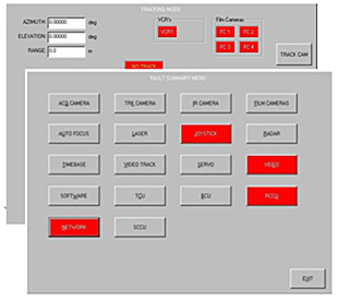
Pedestal Support Electronics — The modularity of the Mini-Sextant control electronics supports several installation scenarios. The Trunnion Computer Unit, vital for real-time operations of the
pedestal, sensors and optics is located within the pedestal. The Digital Servo Amplifier (DSA), RFI power filters and I/O panel are packaged in enclosures at the pedestal site. The remaining
electronics such as Base Computer Unit (BCU), Video Switches, Video Trackers, Video Recorders, etc., are installed in the Operator's Console which can be located in a mobile Operations Van or at
the user’s Mission Operation Center.


Visit The Argus Software Page
Operator Console - Photo-Sonics offers a variety of console configurations, from our full- size console (for location in mission control center) to smaller, compact consoles suitable for mobile command vehicles or multiple packing cases for transportability. The default connection between the pedestal and the remote console is via a single-strand, single-mode 'dark' fiber optic cable, which allows for up to 20 km separation. Alternative interfaces including shared fiber optics and microwave are also supported.
System Options:
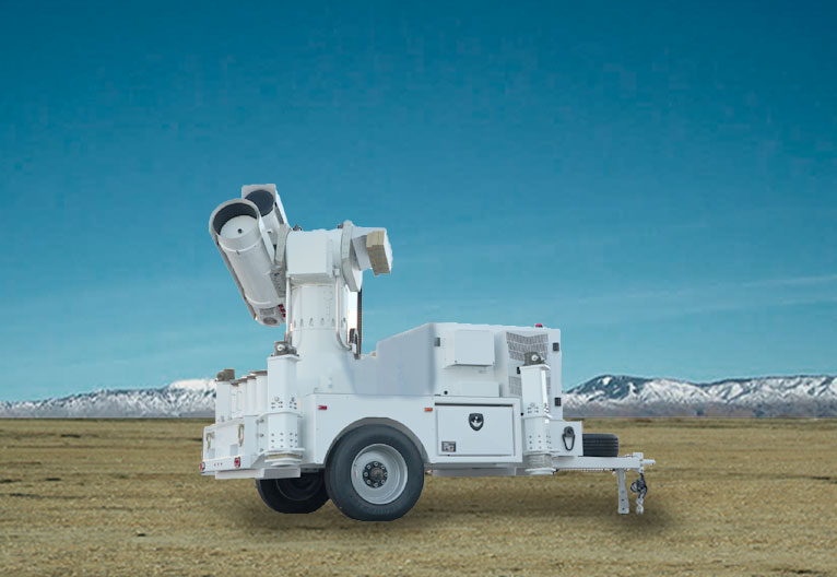
Trailer Configuration The Mini‑Sextant can be configured with a ruggedized trailer system customized for operations at multiple sites.
Shipboard Stabilization Photo-Sonics can configure the Mini-Sextant with a stabilization system to allow use of the system at sea
| 19"Touch Screen Monitor for the main GUI interface | System accuracy, Fixed Mount | 10 arc-seconds (50 micro-radians), 2σ |
| Video Monitors (2,3 or 4 screens available)s | Bearings | 28" diameter azimuth thrust bearing |
| Operator control panel | Drive System | 16” diameter elevation ball bearing |
| Mini keyboard with control | Torque | Azimuth :
350 foot pounds (475 N•m) Elevation: 350 foot pounds (475 N•m) |
| Stick and operator controls | Velocity (Nominal Payload) | Azimuth: 120°/second Elevation : 120°/second |
| Console Computer | Acceleration (Nominal Payload) | Azimuth : 120° sec² Elevation : 120° sec² |
| I/O Panel (Fiebr Optics Ethernet Switches) | Closed Loop Servo Bandwith | Azimuth : 8-10 Hertz Elevation : 8-10 Hertz |
| Optional UPS | Nominal Payload | 200 pounds per platform (at rated payload moment of inertia design specification) |
| Non-Orthogonality Encoders (Optical, Absolute) Elevation Travel |
± 5 arc seconds 24-bit -15° to +195° |
|
| Azimuth Travel | ±270° (Cable wrap configuration) Continuous (slip-ring configuration) |
|
| Transit Locks | -15° to +195° - Locking stow pins in AZ and EL axis | |
| Height | 78” (pedestal base) | |
| Power | 3-phase European or US AC power |
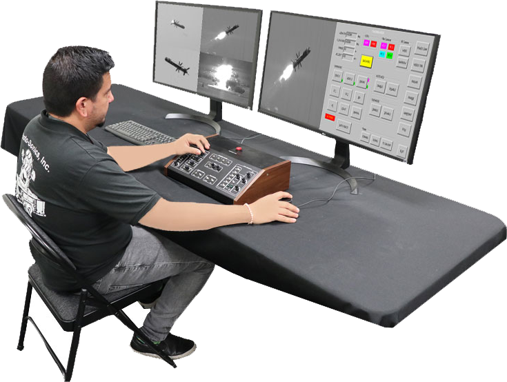
Photo-Sonics, Inc.
818-842-2141 (ph - switchboard paging)
818-842-2610 (fax)
mail@photosonics.com