F/A-18A/B HUD Camera


Visit the Photo-Sonics Video Gallery to view product videos.

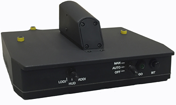
The F/A-18A/B, Head Up Display (HUD) camera is a new configuration operating on the Lot XII and lower series F-18s.

Part Number 93 - 2040 - 501       NSN 5821-01-662-2657       MX-10403A/AXQ
Part Number 93 - 2040 - 502       NSN 5821-01-662-2666       MX-10403B/AXQ

Features
  • The input connector to the camera utilizes the same connector type and the same pin function as the legacy camera.
  • The body of the camera is the same size and utilizes the same mechanical mounting provisions used on the legacy camera.
  • The GO indicator lamp is Night Vision Goggle (NVG) compatible.
  • The camera looks into the HUD-combining glasses and accurately records the HUD symbology and outside world, permitting accurate recording of “what the pilot saw.”
  • General Specifications
  • Automatic Exposure Control with lens iris
  • Adjustable air-to-ground exposure lock (0-10 sec)
  • Visual event mark, completion of GRD
  • 115 VAC, 85 to 265 VAC, 47-440 Hz, Single Phase “C”
  • Pickup device: Interline-transfer hyper HAD CCD, 1/3”
  • Horizontal resolution: ◊ NTSC: 470 TV lines
  • Picture elements: ◊ NTSC: 768(h) x 494(v)
  • Switches on camera to control VCR
  • S/N ratio: ◊ NTSC: >-48dB
  • Sensitivity: 2000 Lux at f/11.00
  • Automatic AGC
  • Minimum sensitivity: 0.975 Lux AGC-On
  • Shutter speeds: 1/60th second, 1/100,000 second, flickerless, and CCD iris (AEC), Off for F-18
  • Gamma: 0.45/1
  • White balance: ATW
  • Video formats: Y/C component and NTSC composite (NTSC used on F-18)
  • Weight: 2 lb 6 oz
  • 12 month warranty

    Environmental Specifications*

  • Vibration (non-gunfire) random/sine low frequency region V-FF-3. Perform vibration. Equipment was operating and monitored during testing.
  • Vibration (gunfire) sine test schedule (total time each axis – 150 min)
  • Vibration (gunfire) sine test levels. Perform sine vibration. Total time in each axis was 150 minutes.
  • Vibration (non-gunfire) random test levels. Perform endurance levels 120 minutes each axis. Equipment was operating and monitored during testing.
  • Service shock (longitudinal, vertical and lateral). Perform 6 total shocks, 3 in each direction for each test. Figure 4-3.2: Service shock test requirements / Shock response spectrum region S-FF-2.
  • Crash safety (Perform crash safety per Fig 4-5). Crash test requirements. All shock regions.
  • Thermal non-operating thermal cycling: -57°C. Dwell for a period of 2 hrs. Raise the temperature to +125°C and dwell for 16 hrs.
  • Operating thermal cycling: -40°C. Dwell for a period of 2 hrs. Raise the temperature to +71°C and dwell for 16 hrs. Raise the chamber temperature to +85°C and dwell for 30 minutes.
  • Thermal shock: Perform thermal shock per MIL-STD-810C Method 503.1. Three thermal cycles from +71°C to –57°C with a 5 minute maximum transfer time and a 4 hr dwell at each temperature plateau.
  • Altitude: Normal operating – test per MIL-STD-810F, Procedure 2. Reduce pressure at a rate not to exceed 2,000 Ft/min to an altitude of 50,000 ft. Dwell for a period of 1 hr.
  • Explosive decompression: Test per MIL-STD-810F, Procedure 4. Reduce chamber pressure to 2,437m (8,000 ft), then in <0.1> seconds reduce pressure to an altitude of 12,192 m (40,000 ft). Maintain this pressure for 10 minutes.
  • Salt and fog: Test per MIL-STD-810F, Method 509.4. Perform 2 cycles of salt fog of 24 hrs and 24 hrs drying per cycle.
  • Explosive atmosphere: Test per MIL-STD-810F, Method 511.4, Procedure 1 (operation in explosive atmosphere).
  • * Based on similarity to tests conducted on F/A-18/C/D/E/F

    FOV Horizontal Degrees Vertical FOV Horizontal Milliradians Vertical Application
    22.06 16.63 384.9 290.3 HUD Special

    Boresighted to all US Navy requirements

    Airborne Video Sales
    818-531-3206
    818-842-2141 (main)
    mail@photosonics.com